Overview
Path interpolation with rotation is similar to regular path interpolation, except a third rotational axis and a center of rotation are defined. During the path interpolation, the rotational axis will rotate the entire path as the direction of motion along the path changes.
Path interpolation with rotation is used for mechanisms consisting of two-dimensional motion in the X and Y axes and a rotational axis that rotates the entire X and Y axes around a center of rotation. The X, Y, and rotational axes can be commanded to move along a path with the following properties:
The path is defined in the X-Y plane, and is composed of linear and circular segments.
The rotational axis will rotate continuously so that it always faces the direction of motion along the path.
The X and Y axes will follow the path using the specified profile parameters (velocity, acceleration, etc.).
The motion of the rotational axis will rotate the X and Y axes around the center of rotation. Offsets are automatically applied to the X and Y axis position commands so that the axes remain on the path as it is rotated. The movement along the path continues at the specified velocity even as the path rotates.
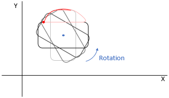
The following diagram illustrates one example of such a mechanism.

Example Sequence of Motions
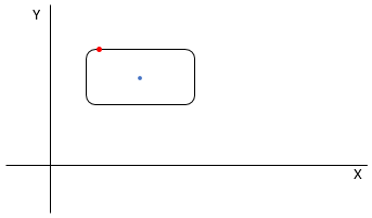
Consider the following path. The blue dot at the center of the path denotes the center of rotation. The red dot is the starting point of the path interpolation.
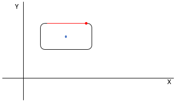
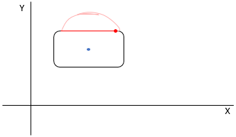
The first step of the path interpolation is a simple linear segment. The red line shows the path of the X and Y axes. The red dot shows the current position.
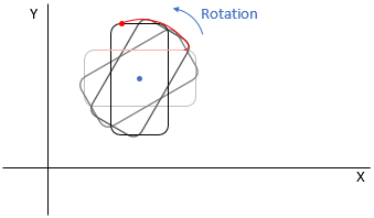
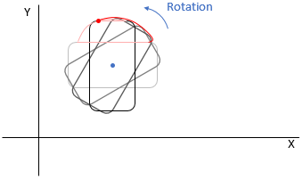
The second step of the path interpolation is a 90-degree arc segment. The rotational axis rotates counterclockwise so that the direction of motion remains the same (in the +X direction). The X and Y axes move along the curve shown by the red line. This curve is the result of compensating for the rotation and moving along the arc segment path.
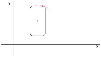
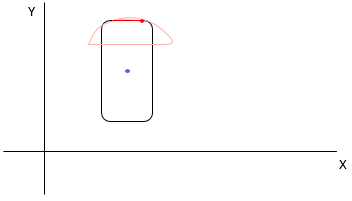
The third step of the path interpolation is another linear segment. The direction of motion is in the +X direction due to the rotation from the previous step.
The fourth step of the path interpolation is another 90-degree arc segment. The X and Y axes move along the curve shown by the red line. This curve is the result of compensating for the rotation and moving along the arc segment path.
The fifth step of the path interpolation is another linear segment. The direction of motion is in the +X direction due to the rotation from the previous step.
The sixth step of the path interpolation is another 90-degree arc segment. The X and Y axes move along the curve shown by the red line. This curve is the result of compensating for the rotation and moving along the arc segment path.
The seventh step of the path interpolation is another linear segment. The direction of motion is in the +X direction due to the rotation from the previous step.
The eighth step of the path interpolation is another 90-degree arc segment. The X and Y axes move along the curve shown by the red line. This curve is the result of compensating for the rotation and moving along the arc segment path. This completes the path interpolation.

Note that the center of rotation does not have to be at the center of the shape of the path. It can be anywhere inside or outside the shape of the path.
Sequence of Function Calls
To execute path interpolation with rotation, four functions must be called in the following order:
CreatePathIntplWithRotationBuffer
This function allocates the buffer memory space that stores the command data for path interpolation with rotation. Once buffer memory space is allocated for a path interpolation with rotation channel with this function, this function does not need to be called again until the engine is restarted. This function may fail if contiguous memory of the specified size could not be obtained from the system. For deterministic behavior, this function should be called during the initialization of the user application instead of immediately before executing the path interpolation with rotation motion. For additional information, see Function Calls Related to Memory Allocation.
SetPathIntplWithRotationConfiguration
This function configures the options for path interpolation with rotation. This function must be called before a path interpolation with rotation commands can be added.
AddPathIntplWithRotationCommand
This function adds path interpolation with rotation commands to a path interpolation with rotation channel. This function must be called before starting the execution of a path interpolation with rotation. After the path interpolation with rotation starts executing, additional commands may not be added until the path interpolation with rotation finishes executing or is stopped and the command data is cleared. This function also sets the starting positions of the X, Y, and rotational axes when it is called for the first time after creating or clearing the path interpolation with rotation buffer. After the starting positions of the X, Y, and rotational axes are set, moving the X, Y, or rotational axis before starting path interpolation with rotation will cause the StartPathIntplWithRotation function to return an error.
-
This function starts the execution of path interpolation with rotation. Calling this function will start the motion of the commanded axes. There are several overloaded versions of this function that allows for additional options such as specifying the target position or point in the path to move to, or setting a trigger condition for starting the motion of the axes.