Overview
Path interpolation is a type of interpolation that combines several linear and circular segments into a two-dimensional path.
When a path interpolation command is executed, the two interpolating axes will follow the defined path trajectory using either a single motion profile or a different motion profile for each segment. If a single motion profile is used, the axes will accelerate to the profile velocity at the beginning of the path and decelerate to a stop at the end of the path.
Linear segments are defined by the absolute or relative target positions of each axis. Circular segments are defined by the absolute or relative target positions and center positions of each axis.
To execute a path interpolation, a buffer memory for storing segment data must be allocated. Each buffer memory is assigned to an axis, and the buffer memory of the first axis of the path interpolation (axis[0]) is the one that is used to execute the interpolation. The buffer memory for the second or third axis of the path interpolation are ignored.
Buffer memory is allocated with the CreatePathIntplBuffer function. If the path interpolation is started with the StartPathIntplPos, StartPathIntplMov, StartPathIntpl3DPos, or StartPathIntpl3DMov function before allocating buffer memory, a default size buffer memory (of size maxPathInterpolateAppendPoints) is allocated. However, allocating buffer memory this way is not recommended because there is always a possibility that any memory allocation will fail. For additional information, see Function Calls Related to Memory Allocation.
To execute a path interpolation containing more than maxPathInterpolateAppendPoints segments, additional segment data must be specified using the optional arguments of the path interpolation function.
Path Interpolation Example
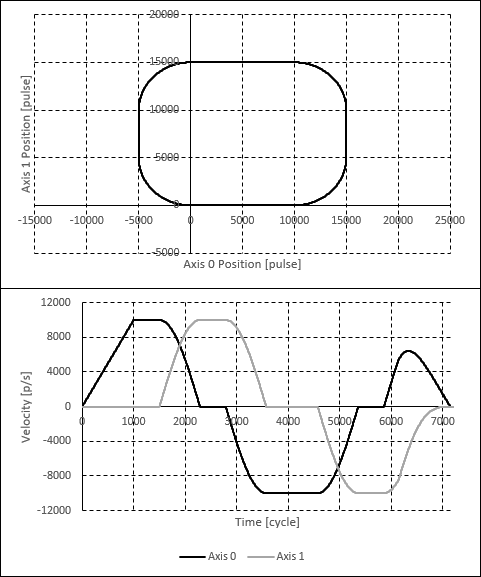
The following code executes a simple path interpolation consisting of four linear and four arc segments. The path interpolation is set to use a single motion profile.
AdvMotion::PathIntplCommand path;

path.axis[0] = 0;
path.axis[1] = 1;

//Use single motion profile for entire path
path.enableConstProfile = 1;
path.profile[0].type = ProfileType::Trapezoidal;
path.profile[0].velocity = 10000;
path.profile[0].acc = 10000;
path.profile[0].dec = 10000;

//Define linear and circular segments
path.numPoints = 8;

path.type[0] = AdvMotion::PathIntplSegmentType::Linear;
path.target[0][0] = 10000;
path.target[1][0] = 0;

path.type[1] = AdvMotion::PathIntplSegmentType::Circular;
path.target[0][1] = 15000;
path.target[1][1] = 5000;
path.centerPos[0][1] = 10000;
path.centerPos[1][1] = 5000;
path.direction[1] = 1;

path.type[2] = AdvMotion::PathIntplSegmentType::Linear;
path.target[0][2] = 15000;
path.target[1][2] = 10000;

path.type[3] = AdvMotion::PathIntplSegmentType::Circular;
path.target[0][3] = 10000;
path.target[1][3] = 15000;
path.centerPos[0][3] = 10000;
path.centerPos[1][3] = 10000;
path.direction[3] = 1;

path.type[4] = AdvMotion::PathIntplSegmentType::Linear;
path.target[0][4] = 0;
path.target[1][4] = 15000;

path.type[5] = AdvMotion::PathIntplSegmentType::Circular;
path.target[0][5] = -5000;
path.target[1][5] = 10000;
path.centerPos[0][5] = 0;
path.centerPos[1][5] = 10000;
path.direction[5] = 1;

path.type[6] = AdvMotion::PathIntplSegmentType::Linear;
path.target[0][6] = -5000;
path.target[1][6] = 5000;

path.type[7] = AdvMotion::PathIntplSegmentType::Circular;
path.target[0][7] = 0;
path.target[1][7] = 0;
path.centerPos[0][7] = 0;
path.centerPos[1][7] = 5000;
path.direction[7] = 1;

wmxlib_AdvancedMotion->advMotion->StartPathIntplPos(&path);
The following plots show the positions and velocities when the above code is executed.