Limit Switches During Homing
Limit switches (hardware limit, near limit, and external limit) behave differently during homing for the following home types.
HS, HSZPulse, HSReverseZPulse, HSHS, HSTouchProbe, HSOff, HSOffZPulse, HSOffReverseZPulse
The limit switch in the direction of homing will not perform the action specified by the LS Type.
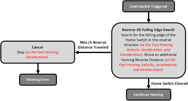
Instead, when the limit switch in the direction of homing is triggered, the axis will reverse and search for the falling edge of the home switch. If the falling edge of the home switch is found before the Max LS Reverse Distance is traveled, the axis will move an additional Homing Reverse Distance and then start the homing procedure.
State Diagram
The following state diagram shows the procedure when the limit switch in the direction of homing is triggered for the above home types.
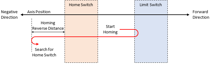
Position Diagram
The following position diagram shows the movement of the axis when a limit switch is triggered.
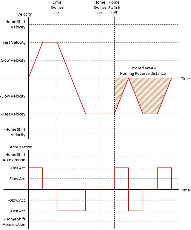
Profile
The following are the velocity and acceleration plots for the above motion.
This procedure will only occur when a limit switch in the direction of homing is triggered. When a limit switch in the direction opposite to the direction of homing is triggered, the limit switch will behave normally.
The hardware limit switch in the direction of homing is used during the homing procedure. The near and external limit switches in the direction of homing are ignored. All limit switches opposite to the direction of homing behave normally.
The near limit switch in the direction of homing is used during the homing procedure. The external limit switch in the direction of homing is ignored. The hardware limit switch in the direction of homing and all limit switches opposite to the direction of homing behave normally.
ExternalLSReverseZPulse, ExternalLS
The external limit switch in the direction of homing is used during the homing procedure. The near limit switch in the direction of homing is ignored. The hardware limit switch in the direction of homing and all limit switches opposite to the direction of homing behave normally.