Prevent Catch Up Motion
If the Prevent Catch Up Motion parameter is set to true, the initial offset when two-dimensional pitch error compensation is enabled will not cause the compensation axis to move. Instead of executing a catch up motion, the command position of the compensation axis is adjusted so that the compensated command position that is sent to the servo does not change. The compensation axes of other two-dimensional pitch error compensation channels may need to be adjusted as well.
Compared to regular pitch error compensation, preventing the catch up motion is more complex when starting two-dimensional pitch error compensation, as changing the command position of one axis can affect the offsets of multiple two-dimensional pitch error compensation channels. As a result, the Prevent Catch Up Motion parameter will only work with the channel configurations discussed below. For other channel configurations, catch up motion will be executed even if Prevent Catch Up Motion is set to true.
In the discussion below, X, Y, and Z are used as axis numbers. Any axis number between 0 and maxAxes - 1 can be substituted for these symbols. Also, A, B, C, and D are used as channel numbers. Any two-dimensional pitch error compensation channel between 0 and max2dPitchErrorCompChannel - 1 can be substituted for these symbols.
For each configuration, the channels may be enabled in any order.
For certain two-dimensional pitch error compensation parameters and axis positions, this function may fail to find a command position that does not move the axis. This typically occurs if the pitch compensation values are unusually large and greater than the pitch interval of one or more reference axes. If a valid command position cannot be found, the command position is not changed and the initial offset is applied with a catch up motion.
Channels With Independent Compensation Axes
Any number of two-dimensional pitch error compensation channels for which the compensation axis is not one of the reference axis of that channel or any other channel may be defined. The reference axes of these channels can be any axis, including axes that are part of one of the configurations discussed below.
1 Channel
The Prevent Catch Up Motion parameter supports single channels for which the compensation axis is one of the reference axes.
The following configurations are supported.
Configuration 1
Channel A
Axis = X
ReferenceAxis[0] = X
ReferenceAxis[1] = Y
Configuration 2
Channel A
Axis = X
ReferenceAxis[0] = Y
ReferenceAxis[1] = X
Any number of two-dimensional pitch error compensation channels may be defined in the above configurations as long as any axis used in one channel (as the compensation axis or reference axis) is not used in another channel. If two or more channels share compensation or reference axes, they must be in one of the configurations discussed below.
The following figure shows the change in the command position when enabling two-dimensional pitch error compensation for these configurations.
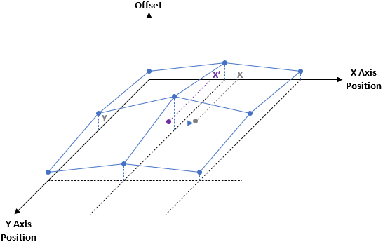
The axes of this plot are X Axis Position, Y Axis Position, and Offset.
The blue points represent the pitch compensation values that are applied to the X Axis.
The blue arrow represents the offset applied to the X Axis at position (X’, Y).
The positions X and Y shown in gray are the initial positions of the X Axis and Y Axis before enabling pitch error compensation.
The position X’ shown in purple is the command position of the X Axis after enabling pitch error compensation.
X’ plus the offset at (X’, Y) equals X. Therefore, the compensated command position that is sent to the servo does not change.
2 Channels With 2 Reference Axes
The Prevent Catch Up Motion parameter supports two channels with two reference axes between them in the following configurations.
Configuration 1
Channel A
Axis = X
ReferenceAxis[0] = X
ReferenceAxis[1] = Y

Channel B
Axis = Y
ReferenceAxis[0] = X
ReferenceAxis[1] = Y
These two channels must have the same values for the following parameters:
PitchOriginPosition[0]
PitchOriginPosition[1]
PitchOriginIndex[0]
PitchOriginIndex[1]
PitchInterval[0]
PitchInterval[1]
PitchIntervalDirection[0]
PitchIntervalDirection[1]
PitchCount[0]
PitchCount[1]
EdgeDropoffDistance[0]
EdgeDropoffDistance[1]
In addition, the originPositionType parameter must be set to the default value of Absolute.
The reference axes must be defined in the same order for both channels.
Any number of two-dimensional pitch error compensation channels may be defined in the above configuration as long as any axis used in one group (as the compensation axis or reference axis) is not used in another group.
The following figure shows the change in the command position when enabling two-dimensional pitch error compensation for this configuration.
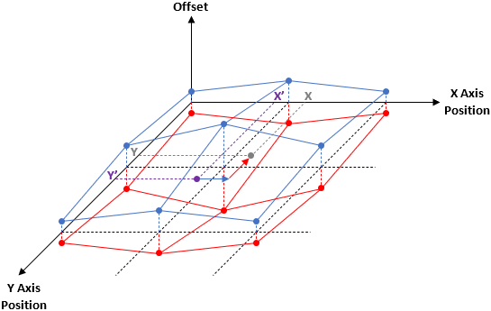
The axes of this plot are X Axis Position, Y Axis Position, and Offset.
The blue points represent the pitch error compensation values that are applied to the X Axis.
The red points represent the pitch error compensation values that are applied to the Y Axis.
The blue arrow represents the offset applied to the X Axis at position (X’, Y’).
The red arrow represents the offset applied to the Y Axis at position (X’, Y’).
The positions X and Y shown in gray are the initial positions of the X Axis and Y Axis before enabling pitch error compensation.
The positions X’ and Y’ shown in purple are the command positions of the X Axis and Y Axis after enabling pitch error compensation.
X’ plus the offset at (X’, Y’) equals X, and Y’ plus the offset at (X’, Y’) equals Y. Therefore, the compensated command positions that are sent to the servo do not change.
3 or More Channels With 2 Reference Axes
The Prevent Catch Up Motion parameter supports three or more channels with the same two reference axes as long as the area in which the offset is defined do not overlap except for pairs of channels in the configuration that was discussed in 2 Channels With 2 Reference Axes.
The offset is defined in the area covered by the pitch points and the Edge Dropoff. If the Edge Dropoff is 0, the offset is defined for all positions and hence only up to a pair of channels in the configuration of 2 Channels With 2 Reference Axes can be defined.
The following is a configuration with two pairs of channels with the same reference axes.
Configuration 1
Channel A
Axis = X
ReferenceAxis[0] = X
ReferenceAxis[1] = Y

Channel B
Axis = Y
ReferenceAxis[0] = X
ReferenceAxis[1] = Y

Channel C
Axis = X
ReferenceAxis[0] = X
ReferenceAxis[1] = Y

Channel D
Axis = Y
ReferenceAxis[0] = X
ReferenceAxis[1] = Y
The reference axes must be defined in the same order for all the channels in this configuration.
The following figure shows two pairs of two-dimensional pitch error compensation channels that do not overlap.

The axes of this plot are X Axis Position, Y Axis Position, and Offset.
The blue points represent the pitch error compensation values that are applied to the X Axis.
The red points represent the pitch error compensation values that are applied to the Y Axis.
The area labeled Compensation Channels 1 and 2 show the offsets applied to the X Axis and Y Axis by the first pair of channels.
The area labeled Compensation Channels 3 and 4 show the offsets applied to the X Axis and Y Axis by the second pair of channels.
4 Channels With 3 Reference Axes
The Prevent Catch Up Motion parameter supports four channels with three reference axes between them in the following configurations.
Configuration 1
Channel A
Axis = X
ReferenceAxis[0] = X
ReferenceAxis[1] = Y

Channel B
Axis = Y
ReferenceAxis[0] = X
ReferenceAxis[1] = Y

Channel C
Axis = X
ReferenceAxis[0] = X
ReferenceAxis[1] = Z

Channel D
Axis = Z
ReferenceAxis[0] = X
ReferenceAxis[1] = Z
Configuration 2
Channel A
Axis = X
ReferenceAxis[0] = X
ReferenceAxis[1] = Y

Channel B
Axis = Y
ReferenceAxis[0] = X
ReferenceAxis[1] = Y

Channel C
Axis = X
ReferenceAxis[0] = Z
ReferenceAxis[1] = X

Channel D
Axis = Z
ReferenceAxis[0] = Z
ReferenceAxis[1] = X
Each pair of channels with the same two reference axes must have the same values for the following parameters:
PitchOriginPosition[0]
PitchOriginPosition[1]
PitchOriginIndex[0]
PitchOriginIndex[1]
PitchInterval[0]
PitchInterval[1]
PitchIntervalDirection[0]
PitchIntervalDirection[1]
PitchCount[0]
PitchCount[1]
EdgeDropoffDistance[0]
EdgeDropoffDistance[1]
In addition, the originPositionType parameter must be set to the default value of Absolute.
The reference axes must be defined in the same order for each pair of channels with the same two reference axes.
Any number of two-dimensional pitch error compensation channels may be defined in the above configurations as long as any axis used in one group (as the compensation axis or reference axis) is not used in another group.
The following figure shows the change in the command position when enabling two-dimensional pitch error compensation for these configurations.
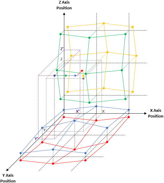
The axes of this plot are X Axis Position, Y Axis Position, and Z Axis Position.
The blue points represent the pitch error compensation values that are applied to the X Axis by the channel with the X Axis and Y Axis as reference axes. The offsets are shown perpendicular to the XY plane.
The red points represent the pitch error compensation values that are applied to the Y Axis by the channel with the X Axis and Y Axis as reference axes. The offsets are shown perpendicular to the XY plane.
The green points represent the pitch error compensation values that are applied to the X Axis by the channel with the X Axis and Z Axis as reference axes. The offsets are shown perpendicular to the XZ plane.
The yellow points represent the pitch error compensation values that are applied to the Z Axis by the channel with the X Axis and Z Axis as reference axes. The offsets are shown perpendicular to the XZ plane.
The blue arrow represents the offset applied to the X Axis at position (X’, Y’, Z’) by the channel with the X Axis and Y Axis as reference axes.
The red arrow represents the offset applied to the Y Axis at position (X’, Y’, Z’) by the channel with the X Axis and Y Axis as reference axes.
The green arrow represents the offset applied to the X Axis at position (X’, Y’, Z’) by the channel with the X Axis and Z Axis as reference axes.
The yellow arrow represents the offset applied to the Z Axis at position (X’, Y’, Z’) by the channel with the X Axis and Z Axis as reference axes.
The positions X, Y, and Z shown in gray are the initial positions of the X Axis, Y Axis, and Z Axis before enabling pitch error compensation.
The positions X’, Y’, and Z’ shown in purple are the command positions of the X Axis, Y Axis, and Z Axis after enabling pitch error compensation.
X’ plus the two offsets at (X’, Y’, Z’) equals X, Y’ plus the offset at (X’, Y’, Z’) equals Y, and Z’ plus the offset at (X’, Y’, Z’) equals Z. Therefore, the compensated command positions that are sent to the servo do not change.