General Statements
In the following descriptions, H represents a hexadecimal number. When specifying a hexadecimal number, it must start with “0x”. D represents a decimal number. 0/1 represents a value that is either 0 or 1.
VendorId: 0xH
Specify the vendor id of the slave that this ENI file should be used for. However, even if this value does not match the vendor id in the file name, the ENI file is used. If the MessageLevel is set to Warning or higher, a mismatch error is printed out to RTXServerConsole.
Example:
VendorId: 0x00009555
ProductCode: 0xH
Specify the product code of the slave that this ENI file should be used for. As with the VendorId, even if this value does not match the product code in the file name, the ENI file is used. If the MessageLevel is set to Warning or higher, a mismatch error is printed out to RTXServerConsole.
Example:
ProductCode: 0x00010101
Alias: 0xH
Specify the alias of the slave that this ENI file should be used for. As with the VendorId, even if this value does not match the alias in the file name, the ENI file is used. If the MessageLevel is set to Warning or higher, a mismatch error is printed out to RTXServerConsole.
Example:
Alias: 0x00000001
Revision: 0xH
Specify the revision number of the slave that this ENI file should be used for. As with the VendorId, even if this value does not match the revision number in the file name, the ENI file is used. If the MessageLevel is set to Warning or higher, a mismatch error is printed out to RTXServerConsole.
Example:
Revision: 0x00032101
Serial: 0xH
Specify the serial number of the slave that this ENI file should be used for. As with the VendorId, even if this value does not match the serial number in the file name, the ENI file is used. If the MessageLevel is set to Warning or higher, a mismatch error is printed out to RTXServerConsole.
Example:
Serial: 0xfa518191
IdentificationReg134: 0/1
0: Slave does not support Explicit Device Identification 1: Slave supports Explicit Device Identification according to ETG.1020/ETG.1000
Example:
IdentificationReg134: 1
IdentificationAdo: 0xH
Specify the register address where the Identification ID is saved.
Example:
IdentificationAdo: 0x1003
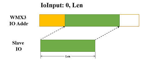
IoInput: offset, size
offset: Specify the offset from where the slave Io input will be mapped to the WMX3 Io input addresses. Decimal.size: Specify the size of the slave Io input which will be mapped to the WMX3 Io input addresses. Decimal.
The offset is specified as the offset within the TxPdo of this slave. Any data in the slave TxPdo can be mapped to WMX3 Io input addresses.
The WMX3 Io input addresses to which a slave’s data is mapped can be checked with the inputAddr and inputSize data that can be obtained with the GetMasterInfo function.
Example:
IoInput: 0, 2
IoOutput: offset, size
offset: Specify the offset from where the slave Io output will be mapped to the WMX3 Io output addresses. Decimal.size: Specify the size of the slave Io output which will be mapped to the WMX3 Io output addresses. Decimal.
The offset is specified as the offset within the RxPdo of this slave. Any data in the slave RxPdo can be mapped to WMX3 Io output addresses.
The WMX3 Io output addresses to which a slave’s data is mapped can be checked with the outputAddr and outputSize data that can be obtained with the GetMasterInfo function.
Example:
IoOutput: 0, 2
The following are two examples of IoInput (IoOutput) with different offsets and sizes:
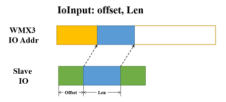
IoInputSeg: offset, size
offset: Specify the offset from where a segment of the slave Io input will be mapped to the WMX3 Io input addresses. Decimal.size: Specify the size of the segment of the slave Io input which will be mapped to the WMX3 Io input addresses. Decimal.
The offset is specified as the offset within the TxPdo of this slave. Any data in the slave TxPdo can be mapped to WMX3 Io input addresses.
The WMX3 Io input addresses to which a slave’s data is mapped can be checked with the inputAddr and inputSize data that can be obtained with the GetMasterInfo function.
Example:
IoInputSeg: 2, 2
IoInputSeg: 0, 2
IoInputSeg: 4, 2
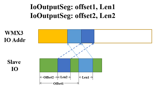
IoOutputSeg: offset, size
offset: Specify the offset from where a segment of the slave Io output will be mapped to the WMX3 Io output addresses. Decimal.size: Specify the size of the segment of the slave Io output which will be mapped to the WMX3 Io output addresses. Decimal.
The offset is specified as the offset within the RxPdo of this slave. Any data in the slave RxPdo can be mapped to WMX3 Io output addresses.
The WMX3 Io output addresses to which a slave’s data is mapped can be checked with the outputAddr and outputSize data that can be obtained with the GetMasterInfo function.
Example:
IoOutputSeg: 6, 2
IoOutputSeg: 3, 2
A maximum of 16 input and 16 output segments can be specified.
The following is a example of the usage of IoOutputSeg.
ComOutChnl: chnlid, offset, size
chnlid: Specify a COM output channel with its id. Decimal.offset: Specify the Pdo offset of this COM output channel. Decimal.size: Specify the Pdo size of this COM output channel. Decimal.
Example:
ComOutChnl: 0, 0, 12
ComOutChnl: 1, 12, 12
ComOutChnl: 2, 24, 12
ComInChnl: chnlid, offset, size
chnlid: Specify a COM input channel with its id. Decimal.offset: Specify the Pdo offset of this COM input channel. Decimal.size: Specify the Pdo size of this COM input channel. Decimal.
Example:
ComInChnl: 0, 0, 12
ComInChnl: 1, 12, 12
ComInChnl: 2, 24, 12
For COM communication, a COM input and a COM output should be set as a pair. A maximum of 8 pairs of COM inputs and outputs can be specified.
DcAssignActive: 0xH
Specify the DC assign active value. This value will be written to register 0x980 to activate the DC function of slave when DCMode is on.
Example:
DcAssignActive: 0x0300
AllowPdoReadWrite: 0/1
0 (Default): Forbid Pdo read/write function for this slave. 1: Allow Pdo read/write function for this slave.
If Pdo read/write function is not allowed, the APIs TxPdoWrite and PdoRead will return an error when they are called.
Example:
AllowPdoReadWrite: 1
FastPdoRead: 0/1
0 (Default): Disable fast PDO read for this slave. 1: Enable fast PDO read for this slave.
Example:
FastPdoRead: 1
AssignToPdi: 0/1
0 (Default): EEPROM access rights are assigned to PDI during state changes from Init to PreOp and from Init to Boot, and while in Boot. 1: EEPROM access rights are assigned to PDI in all states except Init.
Example:
AssignToPdi: 1
LRWSupport: 0/1
0(Default): Disable LRW for all slaves. TxPdo and RxPdo are transmitted by LWR and LRD, respectively. 1: Enable LRW for all slaves. TxPdo and RxPdo are transmitted by LRW.
Example:
LRWSupport: 1
EoEDevice: 0/1
0(Default): Specify the slave is not an EoE device. 1: Specify the slave is an EoE device.
Example:
EoEDevice: 1
EoEIp: D.D.D.D
Specify the IP address for an EoE device.
Example:
EoEIp: 192.168.11.12
EoEMac: D-D-D-D-D-D
Specify the Mac address for an EoE device.
Example:
EoEMac: 00-50-56-a0-00-08
EoEGateway: D.D.D.D
Specify the Gateway IP address for an EoE device.
Example:
EoEGateway: 192.168.11.1
EoESubnetMask: D.D.D.D
Specify the subnet mask for an EoE device.
Example:
EoESubnetMask: 255.255.255.0
S2SCopy: toSlaveId, srcOffset, destOffset, size
Specify a slave to slave copy. The data from source Pdo will be copied to the specified destination Pdo of specified slave every cycle.toSlaveId: Specify the slave id to where data is copied. Decimal.srcOffset: Specify the offset of the source Pdo from where data is copied. Decimal.destOffset: Specify the offset of the destination Pdo to where data is copied. Decimal.size: Specify the data size. Decimal.
Example:
S2SCopy: 2, 0, 0, 4
TxPdo/RxPdo: axisIndex, offset, size
Specify the TxPdo or RxPdo.axisIndex: Specify the axis index in this slave for which this TxPdo/RxPdo is for. Decimal.offset: Specify the offset of this TxPdo/RxPdo. Decimal.size: Specify the size of this TxPdo/RxPdo. Decimal.
Supported RxPdo includes:
ControlWord
ModesOfOperation
TargetPosition
TargetVelocity
TargetTorque
ProfileVelocity
ProfileAcceleration
ProfileDeceleration
MaxTorque
PositiveTorqueLimit
NegativeTorqueLimit
TouchProbeFunction
MaxProfileVelocity
VelocityOffset
TorqueOffset
MaxMotorSpeed
DigitalOutput
TargetVelVoltage
HomingMethod
SpeedDuringSearchForSwitch
SpeedDuringSearchForZero
HomingAcceleration
HomeOffset
Supported TxPdo includes:
StatusWord
ModesOfOperationDisplay
PositionActualValue
VelocityActualValue
TorqueActualValue
ErrorCode
TouchProbeStatus
TouchProbePositionPos1
TouchProbePositionNeg1
TouchProbePositionPos2
TouchProbePositionNeg2
FollowingError
DigitalInput
Example:
ControlWord: 0, 0, 2
ModesOfOperation: 0, 2, 1
TargetTorque: 0, 3, 2
MaxTorque: 0, 5, 2
HomeSwitch: axisIndex, byte, bit
Specify the digital input address which will be used as Home Switch.axisIndex: Specify the axis index in this slave for which the HomeSwitch is specified for. Decimal.byte: Specify the byte of digital input. Decimal.bit: Specify the bit in the specified byte. Decimal.
Example:
HomeSwitch: 0, 1, 2
PosLimitSwitch: axisIndex, byte, bit
Specify the digital input address which will be used as positive limit switch.axisIndex: Specify the axis index in this slave for which the PosLimitSwitch is specified for. Decimal.byte: Specify the byte of digital input. Decimal.bit: Specify the bit in the specified byte. Decimal.
Example:
PosLimitSwitch: 0, 1, 1
NegLimitSwitch: axisIndex, byte, bit
Specify the digital input address which will be used as negative limit switch.axisIndex: Specify the axis index in this slave for which this NegLimitSwitch is specified for. Decimal.byte: Specify the byte of digital input. Decimal.bit: Specify the bit in the specified byte. Decimal.
Example:
NegLimitSwitch: 0, 1, 0
Init2PreOpWaitTime: timeoutPeriodPreOp2InitWaitTime: timeoutPeriodPreOp2SafeOpWaitTime: timeoutPeriodSafeOp2PreOpWaitTime: timeoutPeriodSafeOp2OpWaitTime: timeoutPeriodOp2SafeOpWaitTime: timeoutPeriodtimeoutPeriod: Specify the timeout period in milliseconds. Decimal. Specify the time for which slave state transitions are judged to time out. In the StartCommunication process, if there is a slave whose state transition does not complete even after these time has elapsed, EcPlatform outputs a timeout error on the console screen. Each timeout time defined in the Network Define and applied to the entire network must be greater than the timeout period of each slave.
Example:
Init2PreOpWaitTime: 3000
Name |
Valid Values |
Default Values |
|---|---|---|
Init2PreOpWaitTime |
>= 500, Unit: ms |
6000 |
PreOp2InitWaitTime |
>= 500, Unit: ms |
2000 |
PreOp2SafeOpWaitTime |
>= 500, Unit: ms |
8000 |
SafeOp2PreOpWaitTime |
>= 500, Unit: ms |
2000 |
SafeOp2OpWaitTime |
>= 500, Unit: ms |
3000 |
Op2SafeOpWaitTime |
>= 500, Unit: ms |
2000 |