DC
The Distributed Clock (DC) of EtherCAT slave controllers synchronize the clock between supported slaves and the master. Functionality such as the generation of synchronous output signals (SyncSignals) and precise time stamping of input events (LatchSignals), as well as generation of synchronous interrupts, are supported.
For more information, see “ESC Datasheet Section I - Technology”, Chapter 9.
A DC clock can have 32-bit or 64-bit width. The basic unit is nanosecond.
A 32-bit DC clock can just express over 4.2 seconds. A 64-bit DC clock is enough to express more than 500 years.
Some ESCs only have 32-bit DCs that are compatible with 64-bit DCs.
WMX3 EcPlatform supports 32-bit DC, 64-bit DC, and a mix of both.
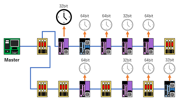
Generally, the clock of the first slave that supports DC is used as the reference clock. The next DC supporting slave synchronizes the clock according to the reference clock.
The offset between the local clock and the reference clock and the propagation delay are measured and set for each slave when communication is started.
The reference clock time is converted by DC slaves every cycle to compensate for clock drift.
The following figure shows the processing timing of the master tasks and slave tasks:
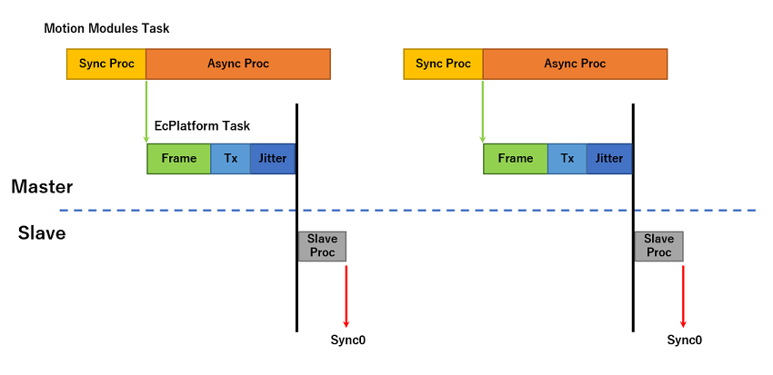
Sync Proc (Motion Module): Synchronous processing time of motion modules. Async Proc (Motion Module): Asynchronous processing time of motion modules. Frame (EcPlatform): Time to unpack PDO data into frame. Tx: Delay time to transfer data from master to slave though NIC driver and Ethernet. Jitter: Mainly depends on the quality of the master timing. Slave Proc: Reserved time for slave processing. Sync0: Synchronization interrupt.
The following table contains the settings related to DC operation.
Name |
Description |
Valid Values |
Default |
|---|---|---|---|
DcMode |
Use DC mode. |
0: DC Off 1: DC On |
1 |
FirstDcSlaveIndex |
Specify the slave to use as the DC master. |
The order index of the slave in the EtherCAT network. Count from 0. |
N/A |
ProcessingDelay |
Specify the PU (Processing Unit) processing time of all slaves. |
Unit: ns |
20 |
ForwardingDelay |
Specify the forward delay of all slaves. |
Unit: ns |
5 |
DcDiffRangeH |
Specify the DC Diff Upper limit. |
0-100, Unit: % |
80 |
DcDiffRangeL |
Specify the DC Diff Lower limit. |
0-100, Unit: % |
60 |
DcDiffShiftRatio |
Shift ratio when adjusting DC Diff. |
1-99, Unit: % |
50 |
DcDiffDetectSlaveId |
Specify the slave id of the slave whose DC diff is detected and printed out to RTXServerConsole when communication is stopped. |
Slave id |
N/A |
DcMode:
0: Disable clock synchronization even if there are DC supported slaves on the network. The master timer is used for packet scheduling.
1: Enable distributed clock synchronization. Use the first DC supported slave as the DC master. Synchronize the timer of the other slaves with the timer of the DC master.
Example:
    DCMode = 1
FirstDcSlaveIndex:
Specify the slave to use as the DC master. The slave index counts from 0. The specified slave does not need to support DC but must have a clock.
Example:
    FirstDcSlaveIndex = 1
ProcessingDelay:
Specify the processing delay of the PU (Processing Unit) used by all slaves to calculate the propagation delay. The default value for the PU processing delay is not accurate enough. Setting ProcessingDelay to a value close to the actual value can help measure an accurate propagation delay, which will increase the accuracy of DC synchronization.
Example:
    ProcessingDelay = 15
ForwardingDelay:
Specify the forwarding delay for the propagation delay calculation in the same way as ProcessingDelay. Processing delays occur when packets are converted through the PU, otherwise forwarding delays occur.
Example:
    ForwardingDelay = 1
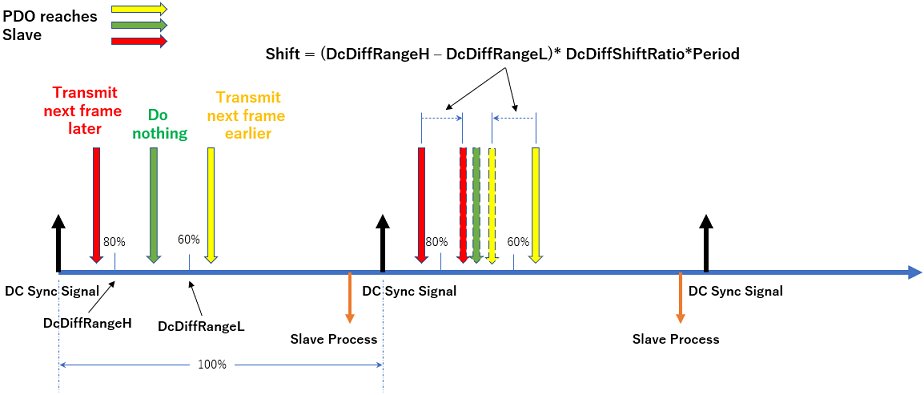
DcDiffRangeH, DcDiffRangeL, DcDiffShiftRatio:
Specify the range to adjust the timing when the PDO data does not reach the first DC slave within this range (the range before the next DC signal). Assuming the DC sync signal period as 100%, DcDiffRangeH defines the upper limit of the range in which if the PDO data reaches the first DC slave, adjustment is not necessary. DcDiffRangeL defines the lower limit of this range. DcDiffShiftRatio specifies the ratio (%) by which the timing is shifted if adjustment is necessary.
If DcDiffRangeL is specified to be greater than or equal to DcDiffRangeH, both specified DcDiffRangeL and DcDiffRangeH will be ignored. In this case, the default values of DcDiffRangeL and DcDiffRangeH will be applied.
Example:
    DcDiffRangeL = 50
    DcDiffRangeH = 70
    DcDiffShiftRatio = 60
DcDiffDetectSlaveId:
Specifies the slave id (counted from 0) whose DC Diff related information is detected and collected during communication. When communication is stopped, the collected information is printed out to RTXServerConsole if PrintLog is set to 1. This function is used to check the DC sync status of the slaves in the network. The printed-out information looks like:
DcDiffDetectSlaveId = 3
    MinDcDiff: 497357
    MaxDcDiff: 813602
    MinDrift: -239
    MaxDrift: 1702
MinDcDiff and MaxDcDiff are the minimum and maximum DC Diff values during communication in units of nanoseconds.
MinDrift and MaxDrift are the minimum and maximum drift between the local clock time of the specified slave and the reference clock time. Minus value means the local time is earlier than the reference time. Plus value means the local time is later than the reference time.
Example:
    DcDiffDetectSlaveId = 3